In the present project, the analysis of vortex formation and air suction into 4 pumps in a power plant pond, where the free water level is filled up to a height of 2.73m, has been analyzed. The SIMPLE model has been used to establish a connection between continuity and momentum equations for calculating the pressure field. Air is considered as the main phase and water as the secondary phase. The results show that based on the height of the free surface and the suction speed of the pump, air can be sucked into the pump. A simple geometry of 5 x 7 meters of single pipes was modeled. Suction of more than 20% for air was observed in the modeling. Finally, appropriate solutions to prevent vortex formation were presented.
Cooling is one of the most critical processes in power plants, necessary to reduce equipment temperature and prevent damage. One cooling method involves using water, where water absorbs heat from the equipment as it passes over them. The heated water is then transferred to a cooling tank, where it is cooled by another cooling fluid (air or water) before re-entering the cooling cycle. The power plant in question has a cooling tank with 5 fans, each 12 meters in diameter, that direct water into a cooling pond. In this pond, there are 5 pipes, each 40 inches in diameter, with pumps at the end. These pumps draw water from the cooling pond at a rate of 4500 cubic meters per second and transfer it to another cooling system. The pumps operate in rotation, and the tank must be designed for efficient cooling and safety.
The geometry of the tank and its blocking are as follows:
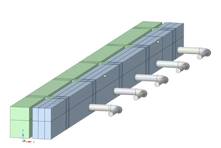
The total length of the pond is 83.2 meters, the width is 2.9 meters, and the total height is 4.75 meters. Water is assumed to be filled up to a height of 2.73 meters from the bottom of the pond. The mesh blocking is arranged to improve network control and to avoid an excessive increase in cells in less important areas.
The flow inside the basin is modeled as an unsteady, three-dimensional, incompressible, and viscous flow with constant physical properties. The governing equations of the problem are the continuity equation (conservation of mass) and the Navier-Stokes equation (conservation of linear momentum).
The pressure distribution across a plane perpendicular to the flow is shown in Figure 1, indicating that the model accurately captured the relevant forces, including gravitational effects.
Figure 12 presents the velocity magnitude distribution, which illustrates the water flow suction from the valves. It also demonstrates an increase in velocity within the reducing tube (reducer) due to the decrease in the cross-sectional area of the tube.